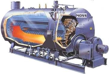
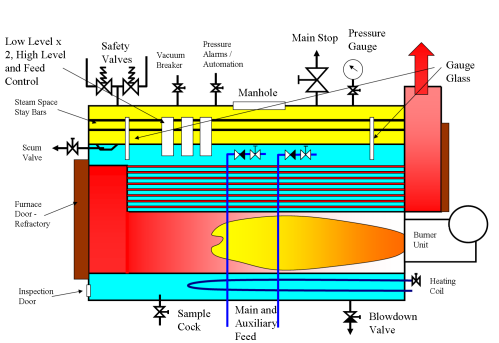
Boiler Fittings
Alat kelengkapan minimumnya adalah:
•Safety valves.
•Water Level indicators.
•Low water alarm and shut down.
•Main Stop valve
•Feed Cheek valves
•Pressure Gauge
•Salinometer Valve
•Blow Down Valve
•Manhole
HSE Rules
9 Water level controls and the first low water alarm which also extinguishes the burner may be housed in the same external chamber or internal protection tube. Additionally a separate chamber or internal protection tube with an independent electrical control circuit is required for an overriding second low water alarm and fuel cut out; this should be a lock‑out type requiring manual reset.
Automatic firing controls so arranged that they effectively control the supply of fuel to the burners on oil or gas fired boilers, or air to solid fuel fired boilers, and effectively shut off the supply in the event of any one or more of the following circumstances:
(iv)when the water level falls to a predetermined point below the normal operating level. When the water level is restored the burner may be automatically refired;
Note: In the case of (i) (ii) and (v), these controls should be of the lock out type requiring manual resetting. In the case of (iv) this control should cut off the fuel/air supply and cause an audible alarm to sound.
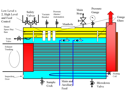
Exhaust Gas Boiler
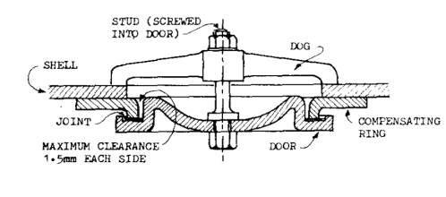
Manhole Door
Water Tube Boiler Components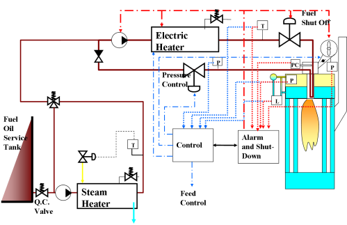
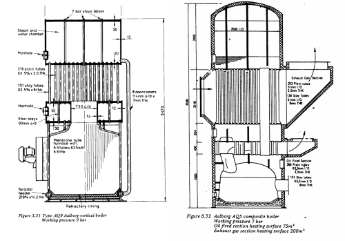


Evaporator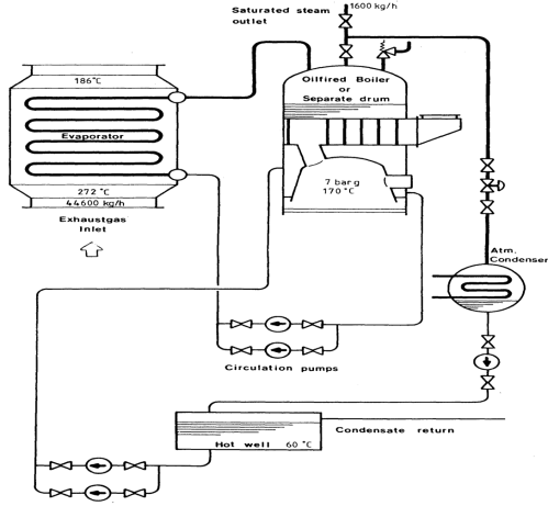

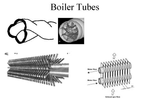
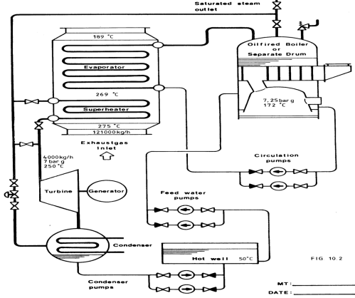
Drain Hole Boiler
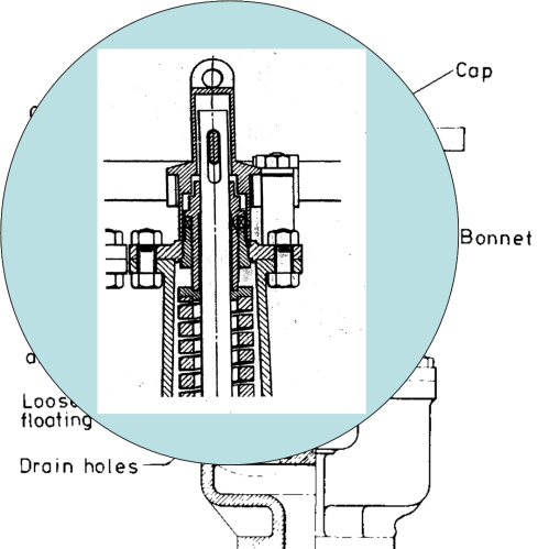
Steam Boiler Valve
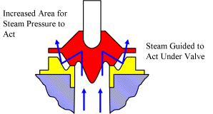
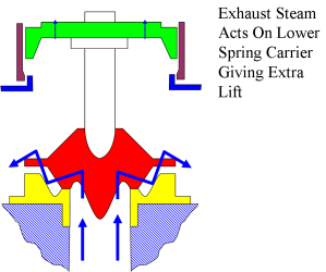
Valve Component
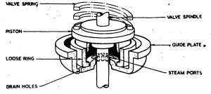
Modified Valve Component
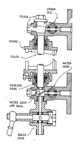
Drain Component
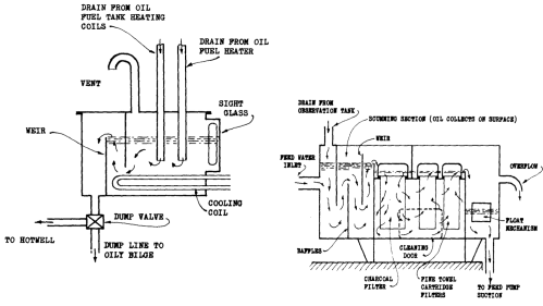
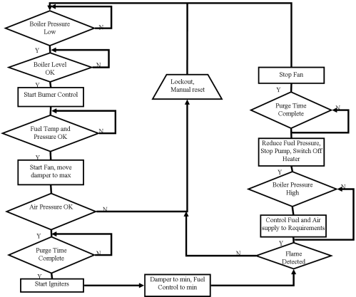
Boiler Operation Flowchart
Uptake Fires
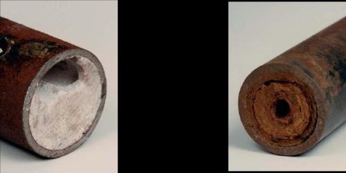
Initial Boiler Entry
•Permit to Work.
•Isolate all fires by shutting off the burner fuel inlets. Close feed inlets
•Let the boiler cool down until about 3‑4 bar steam pressure remains
•Open the blowdown line to empty the boiler drum.
•When about 2 bar pressure remains in the boiler drum open the air vent and leave open
•Prepare to open the manhole doors by loosening nuts and breaking seal when the steam drum pressure has reduced to atmospheric (22.5.1)
•Remove top doors first, and then bottom after ensuring contents drained. Thoroughly ventilate.
•Personnel should not enter boiler, furnace or flue until the unit has cooled sufficiently. (22.5.2)
•Ensure all connections to drum are either blanked off, removed or valves locked in closed position with posted notices. (22.5.3)
•All personnel working on boiler require PPE. (22.5.4)
•Treat the boiler as an enclosed space, so ventilate and test atmosphere for oxygen content (22.5.5)
Oil Contamination Of Boiler
•Change feed to an uncontaminated supply.
•Do not blow down the boiler from the bottom; just surface blow (scum) several times. If you bottom blow the boiler, it will become totally covered in oil.
•The boiler should be shut down and released from pressure and the venting valve opened.
•Drain the boiler slowly until water stops flowing from the loosened, upper manhole door before opening up the manhole for inspection. The oil will now only cover the boiler in the normal water level range and can be manually removed.
•Hot or cold water high-pressure jet equipment together with oil dispersive additives would be efficient for removal of the oil.
•In case the boiler is completely oily inside, the cleaning work should be turned over to a cleaning company specialised in such work. A full alkaline wash of the inside and complete structural inspection would be required.
Boiler Inspection
FIRESIDE
•Loss or refractory
•Condition of the refractory around the burner and the back wall, as these areas suffer from high temperature cracking.
•Distortion to any metal surfaces including the furnace and the tube plates
•Condition of the furnace floor looking for signs of oil contamination
•Signs of overheating at the burner assembly.
•Tube ends for signs of leakage, creep cracking.
WATERSIDE
•Integrity of the bottom blow down pipe and other internal fittings.
•Boiler bottom plate (furnace top‑fire tube boiler), furnace wall for steam bubble pitting
•Mechanical grooving of boilerplates at internal supports
•Oxygen pitting of shell at the water line
•Thinning or necking of the tubes
•Pitting of the boiler tubes
•Feed and scum pipe integrity
•Oxygen pitting in the steam space
•Condition of manhole opening, joint faces, welds, corrosion
•Steam space stay condition.
•Scale deposits
•Condition of welds
•Blockages in pipes for mountings
SHELL
•Condition of lagging
•Signs of leakage
•Fit of manhole door and condition of securing device
•Overhaul all valve and fittings;
•Check for corrosion. All parts should be made from non-corrodable material
•Check valve seat faces free from defects and face width not excessive
•Check valve bodies for corrosion and cracks
•Hang all components and check free from cracks by NDT inspection
•For safety valves
•Check spring length, and carry out NDT inspection
•Check valve spindle straight
•Cheek valve body drain clear
•Check easing gear operation and condition
Refilling And Raising Steam
•Replace all mountings, ensuring correct fitting and direction of flow.
•Replace inspection covers, ensuring securing devices not overightened.
•Refill boiler water, adding correct chemical dosage. Level should be just above Low Level alarm.
•Check operation of level alarms, feed controls, automation pressure switches.
•Ensure all valves are in their working positions, test gauge glasses.
•Check burner controls and cut outs.
•With the vent open, start to warm the boiler. Firing should initially be for short periods (5 mins) with a break (15 mins) to allow the boiler to warm through evenly.
•When steam is coming out of the vent, (2 bar pressure), close vent and bring boiler to working pressure.
•Set safety valves.
•Test all alarms and shutdowns.
•Check tightness of glands and bolts.
•Check tightness of manhole and inspection covers.
Adjustment Of Safety Valves.
•Calibrate pressure gauge and check pipes clear 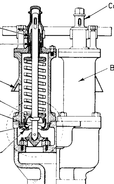

•Raise steam
•Steam outlet closed
•Gag one valve
•Raise pressure and adjust valve to open at required pressure
•Check blowdown
•Change over gag
•Repeat 5 & 6
•Remove gag
•Lock valve adjusters / make and fit spacers
•Recheck opening pressure
•Check easing gear and seal covers
•Check alarms and burner operation
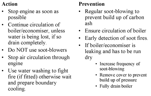
Hydrogen Fires
Conditions Required
•Tube metal temperatures of over 705°C
•Tubes with some steam content (poor circulation)
•The presence of a catalyst in the form of a carbon ash.
Prevention.
•Regular sootblowing to prevent build up of carbon ash
•Ensure circulation of boiler
•If boiler to be run dry, drain and vent to eliminate possibility of steam presence
Fighting.
•Shut of air by gagging turbo blowers – wet canvass over intakes, ensure exhaust valves closed
•Boundary cool
Water Analysis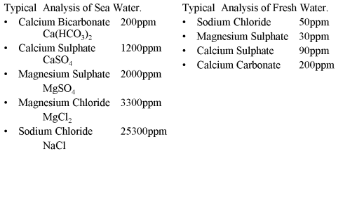

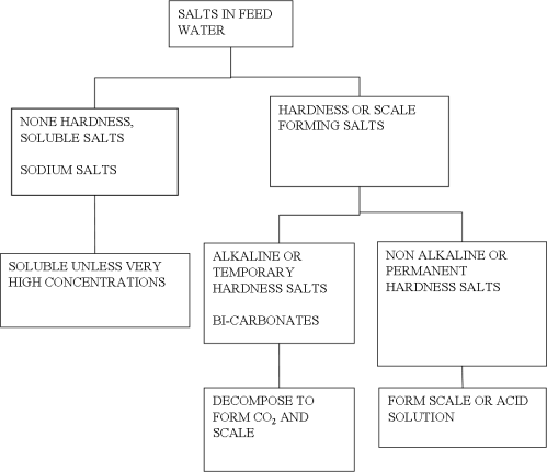
Scale Forming Salts
Magnesium Chloride
Decomposes to form hydroxide and hydrochloric acids. The former will produce hard scale and the later lowers the pH.
MgCl2 + 2H2O ® 2HCl + Mg(OH)2
Magnesium Sulphate
Forms a hard scale on the heating surfaces
Calcium Sulphate
Forms a hard scale on the heating surfaces
Calcium Bi-carbonate
Decomposes at a low temperature when CO2 is liberated. Remaining Calcium carbonate deposits on the heating surface as a soft scale.
Ca(HCO3)2 ® CaCO3 + CO2 + H2O
Boiler Treatment
ALKALIS
•Sodium Carbonate (soda ash).
Reacts with non‑alkaline hardness salts by either precipitating them, or converting into sodium salts, which stay in solution. Excess Sodium carbonate remains in solution to provide an alkalinity to reduce corrosion.
Na2CO3 + CaSO4 ® CaCO3 + Na2SO4
•Sodium Hydroxide. (caustic soda)
Reacts with magnesium chloride producing a harmless precipitant and sodium chloride, which remains in solution.
It is not suitable for pre‑mixing with other chemicals. But can be used in conjunction with other chemical treatments.
2NaOH + MgCl2 ® 2NaCl + Mg(OH)2
PHOSPHATES
•Disodium Phosphate
Dissolves in water and forms a neutral solution. Reacts with magnesium and calcium sulphates and precipitates them as phosphates, or converts them to sodium salts, which will remain in solution.
Na2HPO4 + MgSO4 Þ MgHPO4 + Na2SO4
•Trisodium Phosphate
Dissolves in water to produce disodium phosphate and sodium hydroxide, an alkaline solution.
Na3PO4 + H2O Þ Na2HPO4 + NaOH
• The function of both these chemicals is to prevent scale formation by precipitating the salts of magnesium and calcium as a soft sludge.
•Coagulants (Starch, Tannin, Sodium aluminate)
These chemicals attract the sludges which float in the boiler water. They keep the sludge in suspension and so avoid any build up of sludge on the heating surfaces. Can also help in the reduction of foaming and also keep any oil present in an emulsified form.
•OXYGEN SCAVENGERS
Presence of oxygen in the boiler water will result in serious corrosion.
To reduce the amount of oxygen present in the boiler water oxygen scavengers are used.
These are Hydrazine or Sodium Sulphite
Hydrazine N2H4 + O2 ® 2H2O + N2
Sodium Sulphite 2NaSO3 + O2 ® 2NaSO4
nice website
BalasHapusMost boilers have two sight glasses; both are connected to the boiler at the top and bottom and have notches in the glass to help observe how much water is in the boiler.
BalasHapusboiler cooling treatment service in Ontario